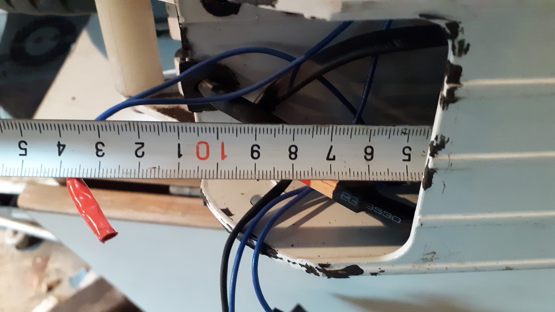
The plan is to mount motor also for the rear wheel to climb the uphill better.
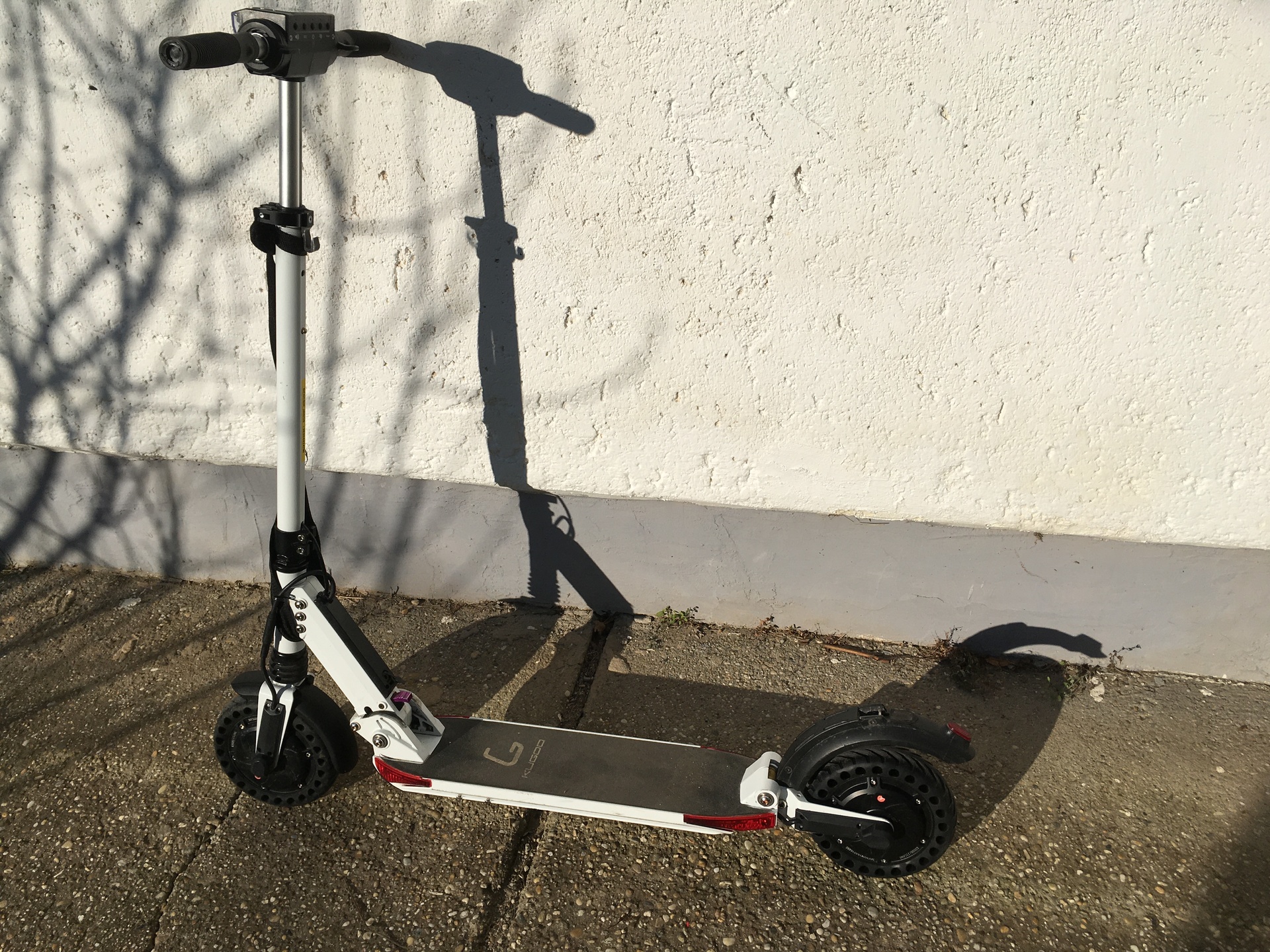
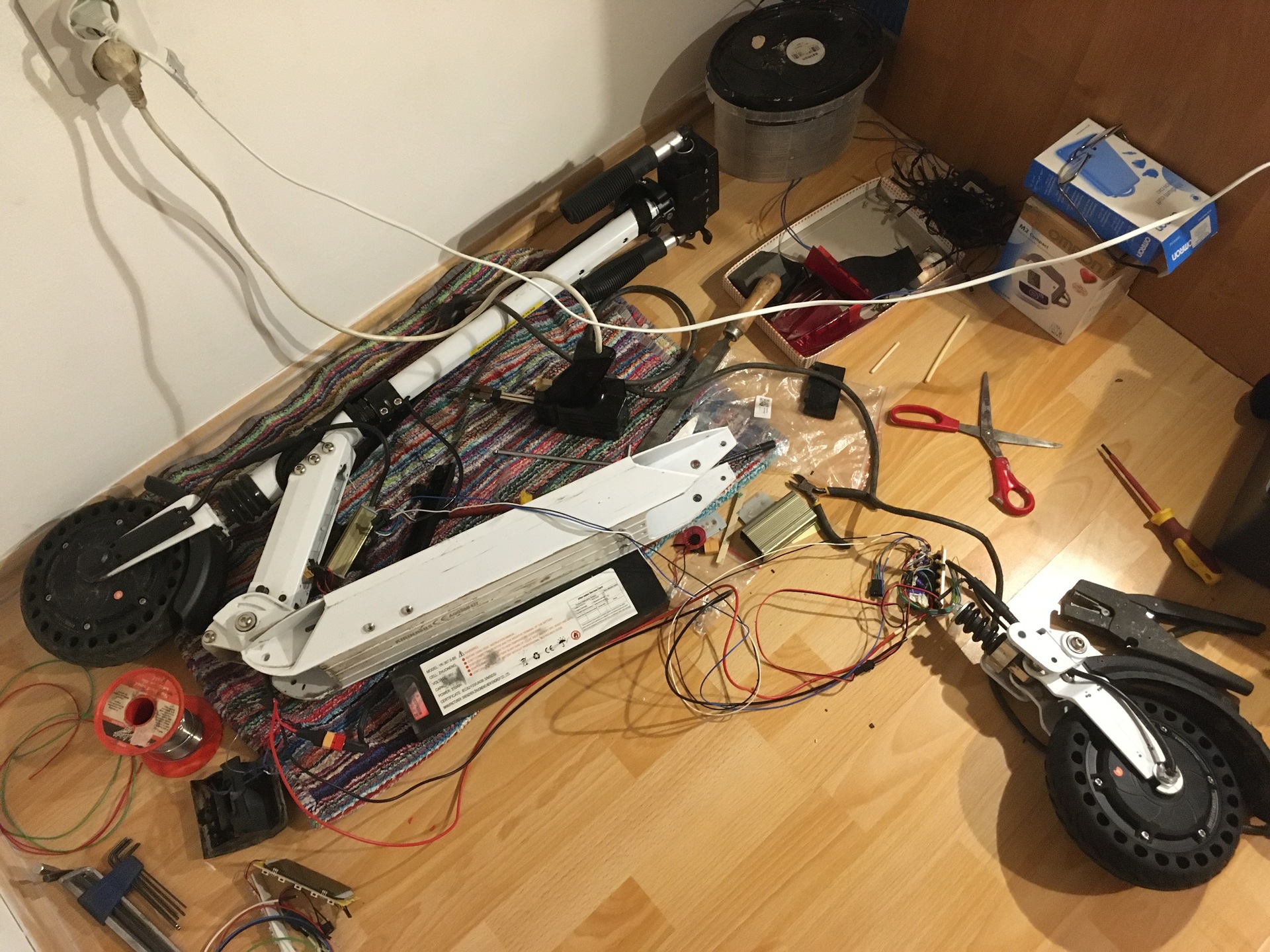
Pictures
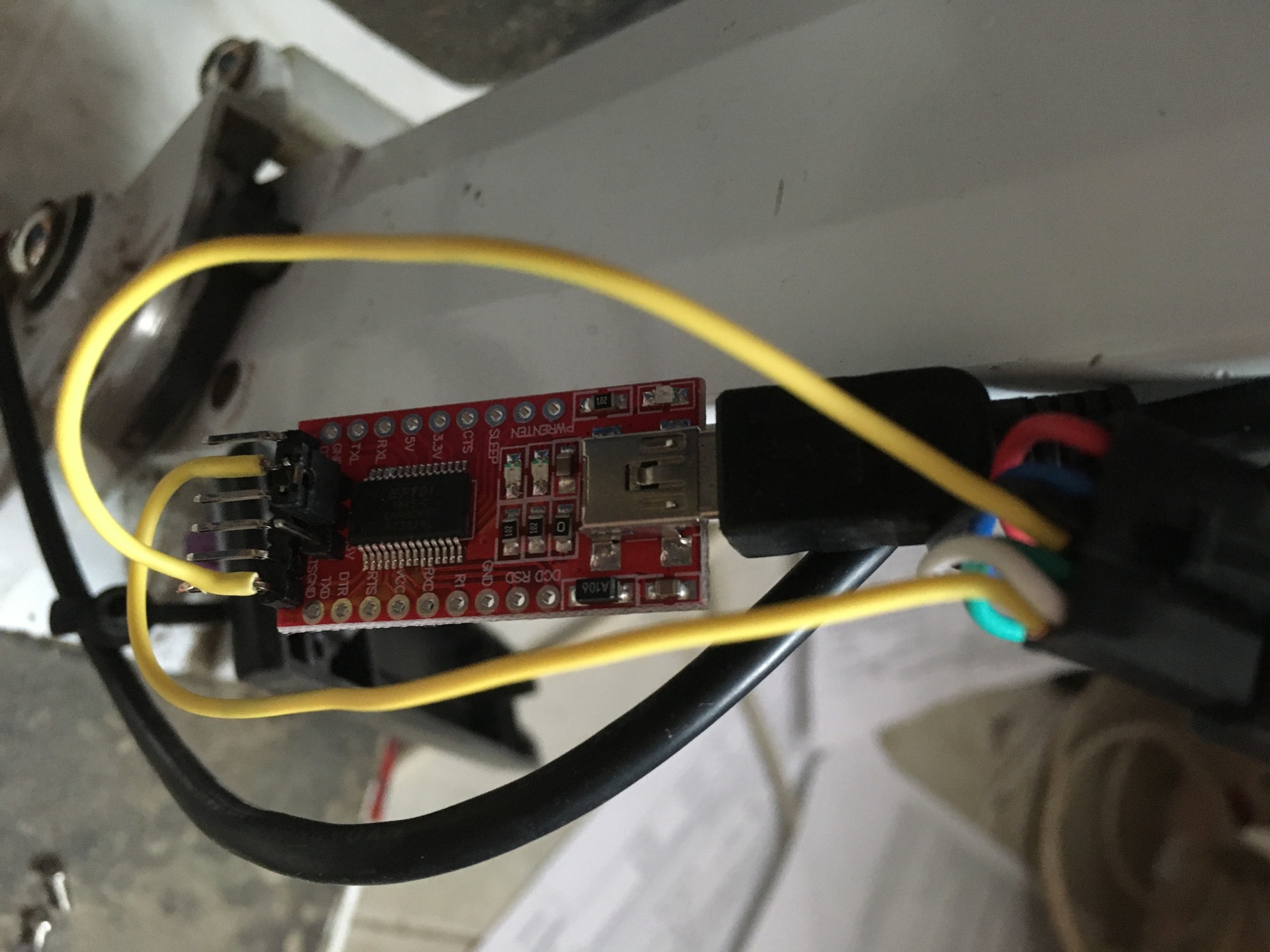
I have ordered a new motor controller and display module. We have investigated the interface between them.
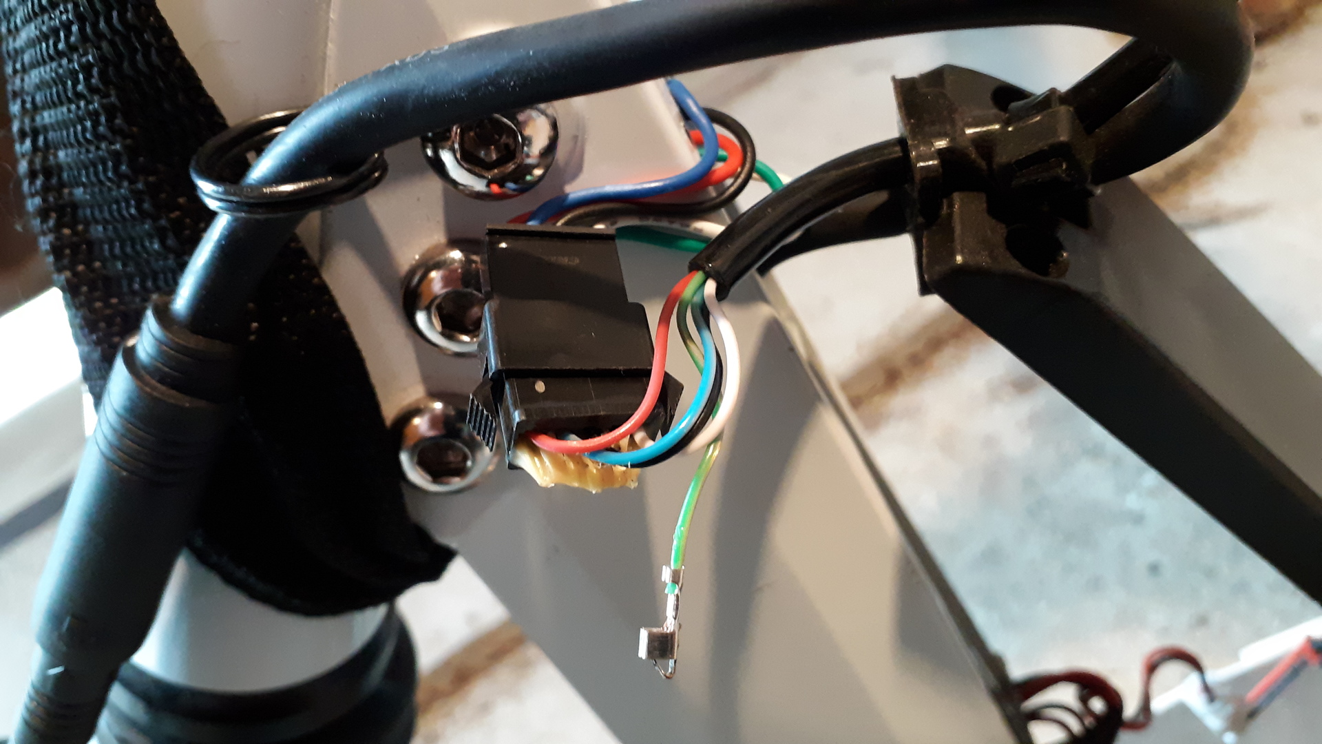
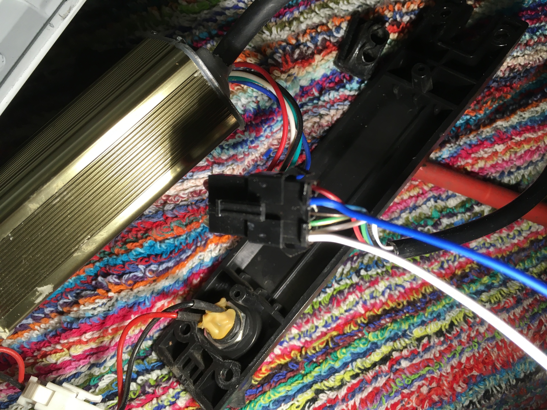
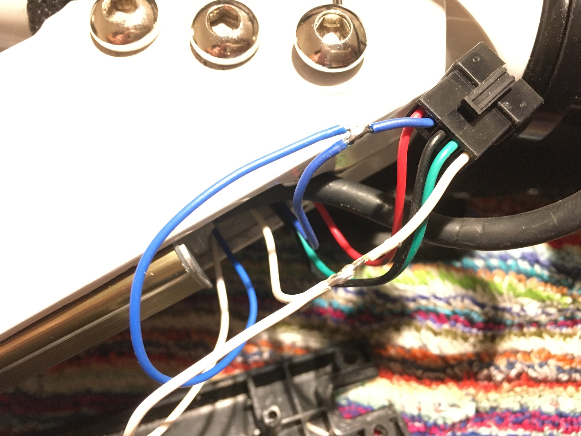
- Black - Ground
- Red - +36V supply voltage
- Blue - +36V switched supply voltage
- Green - Communication from controller to display
- White - Communication from display to controller
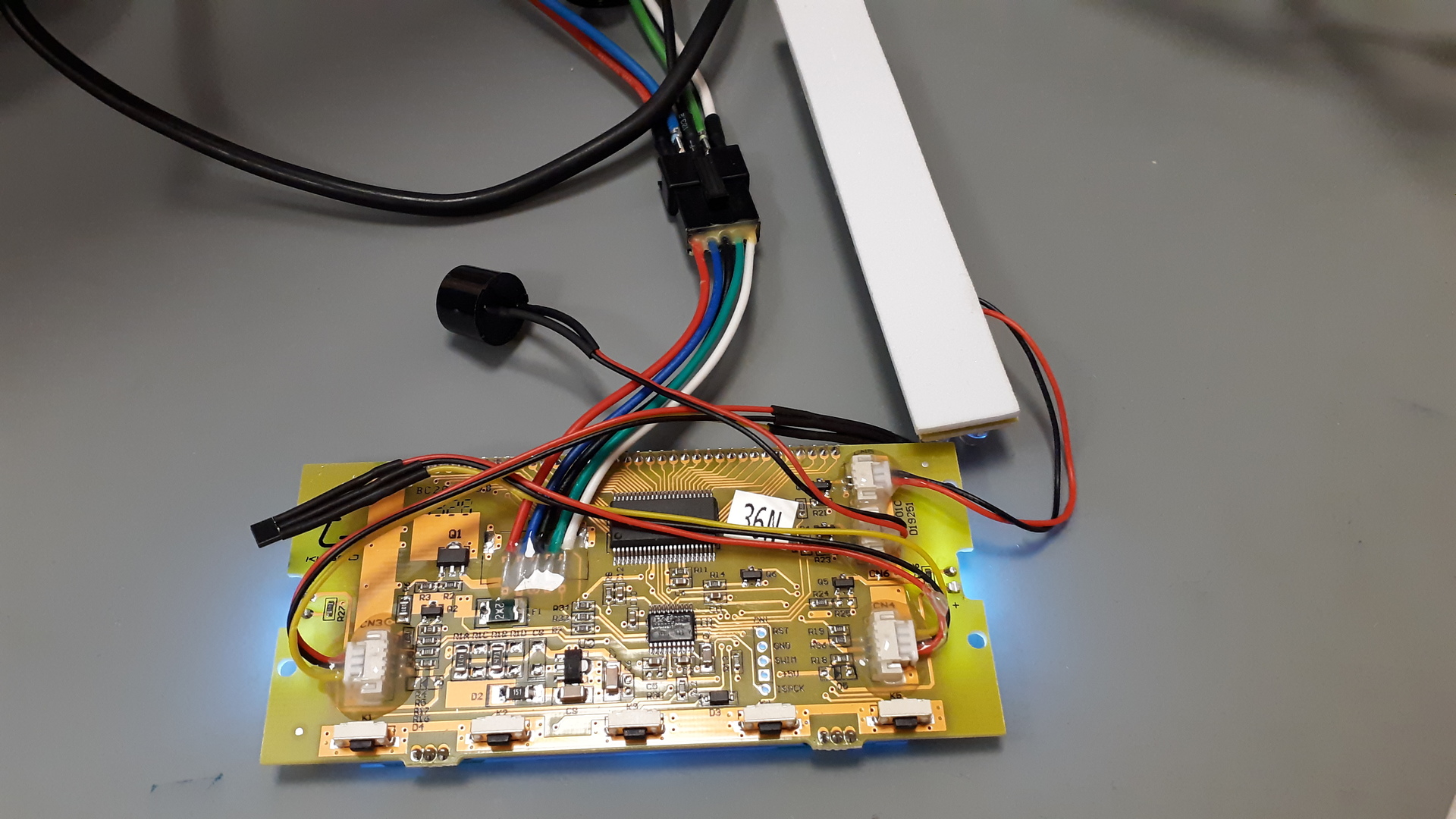
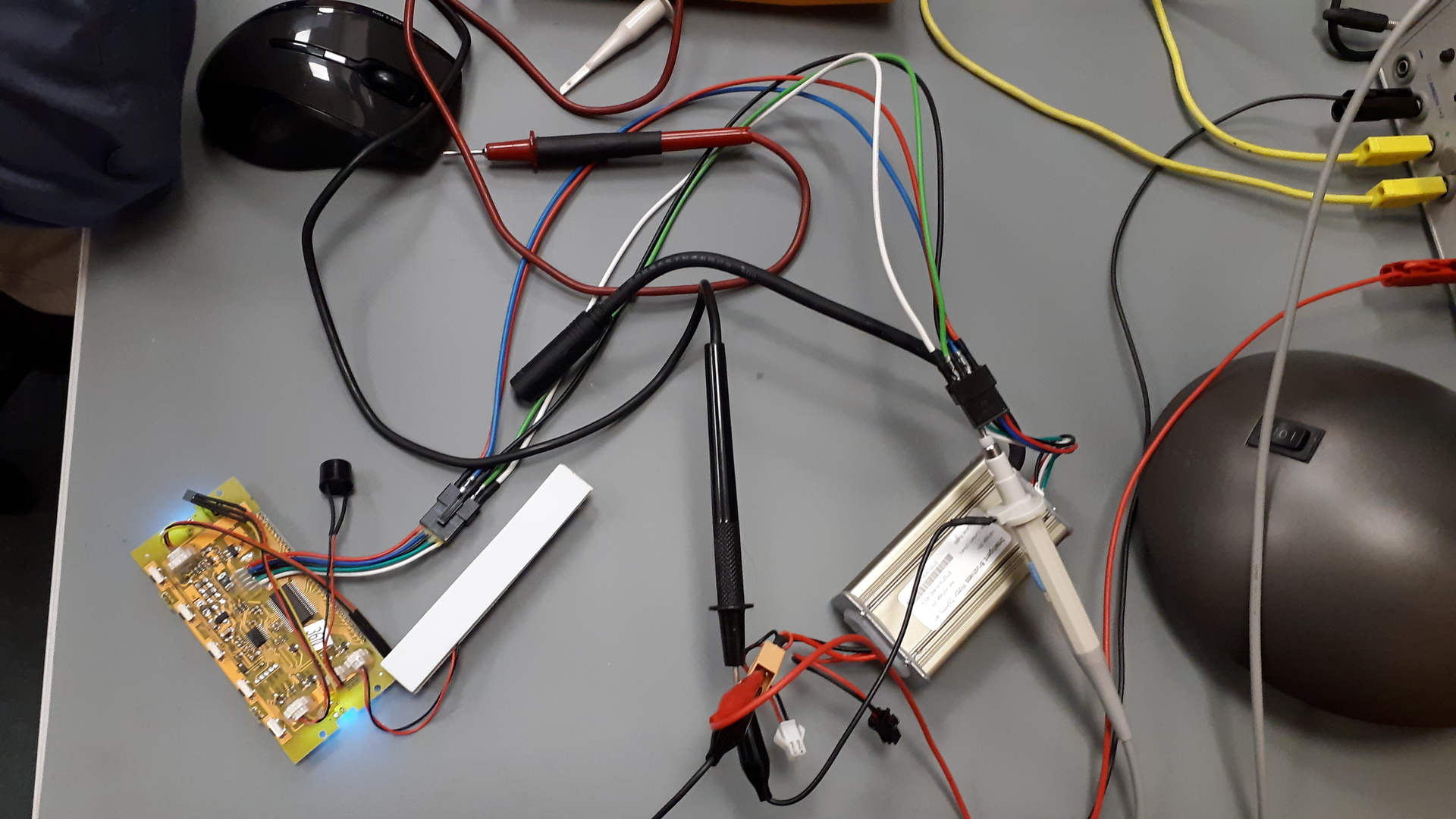
The communication is UART with 9600 baudrate.
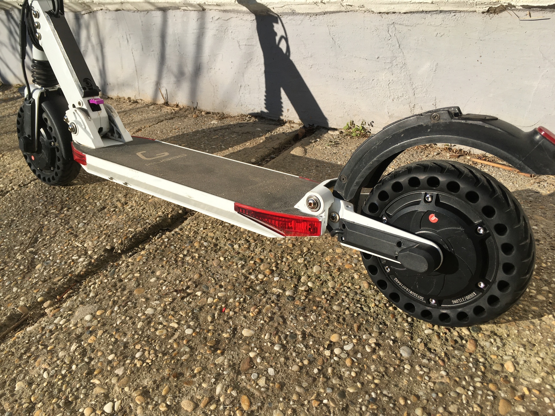
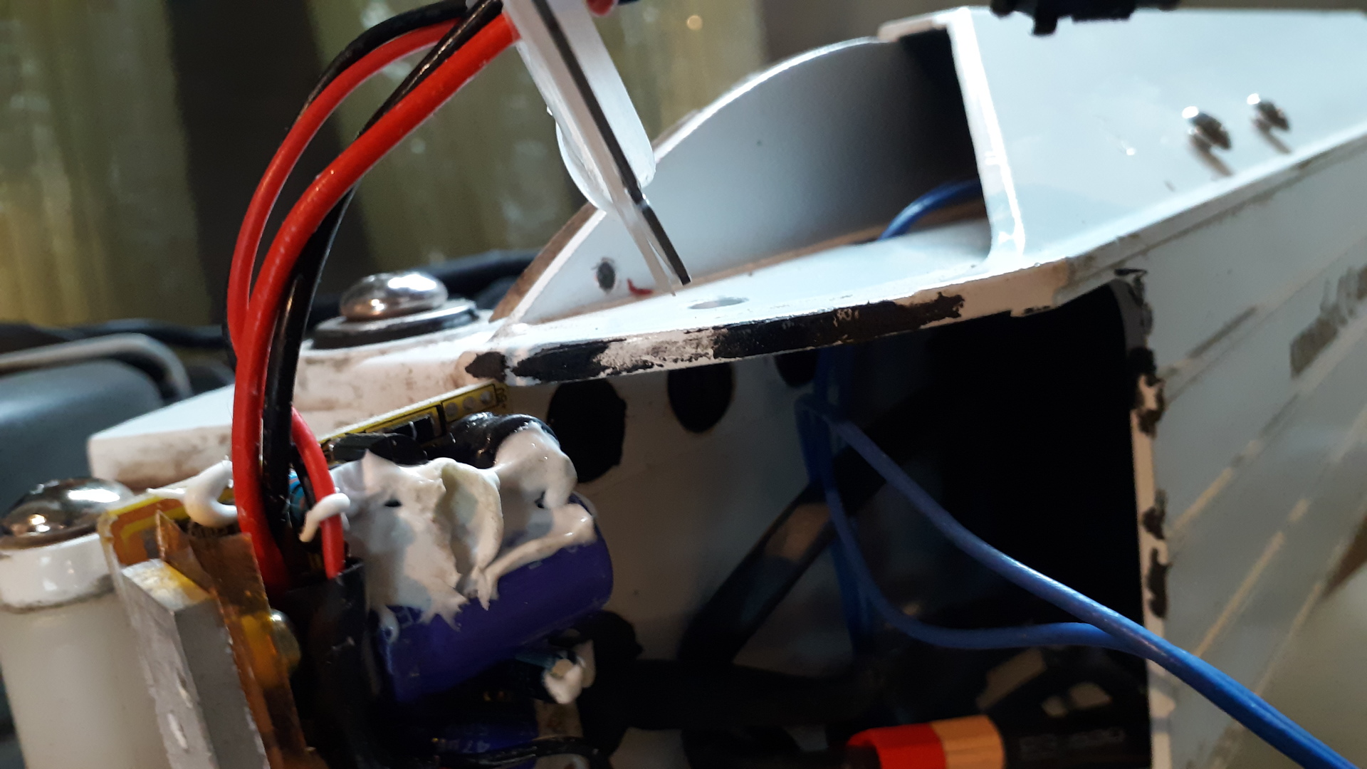
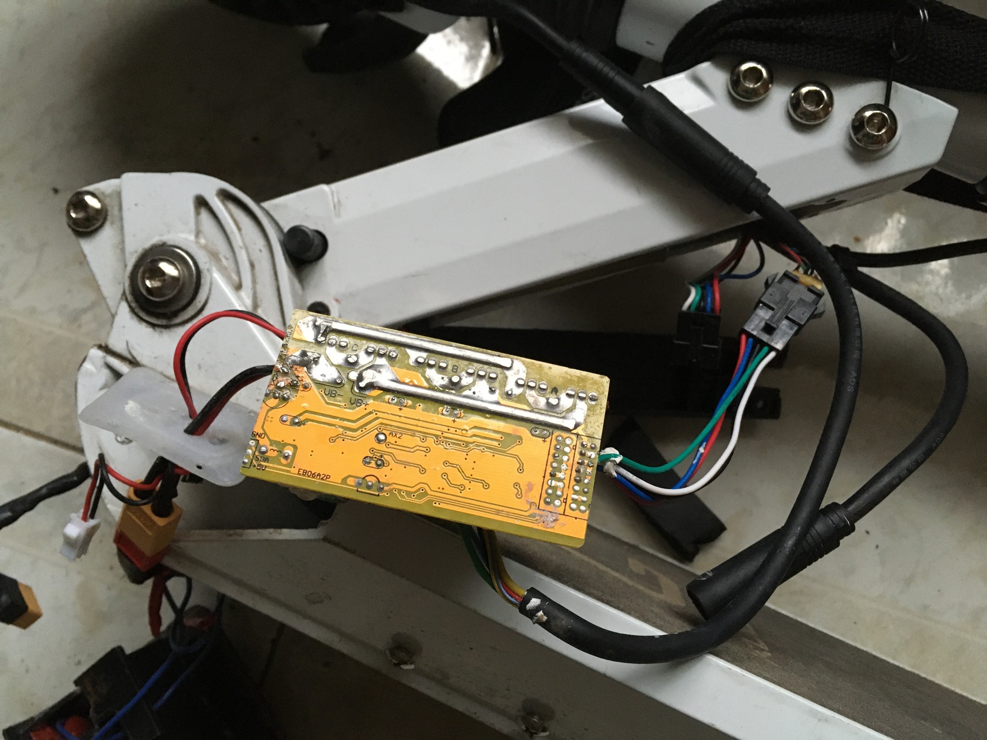
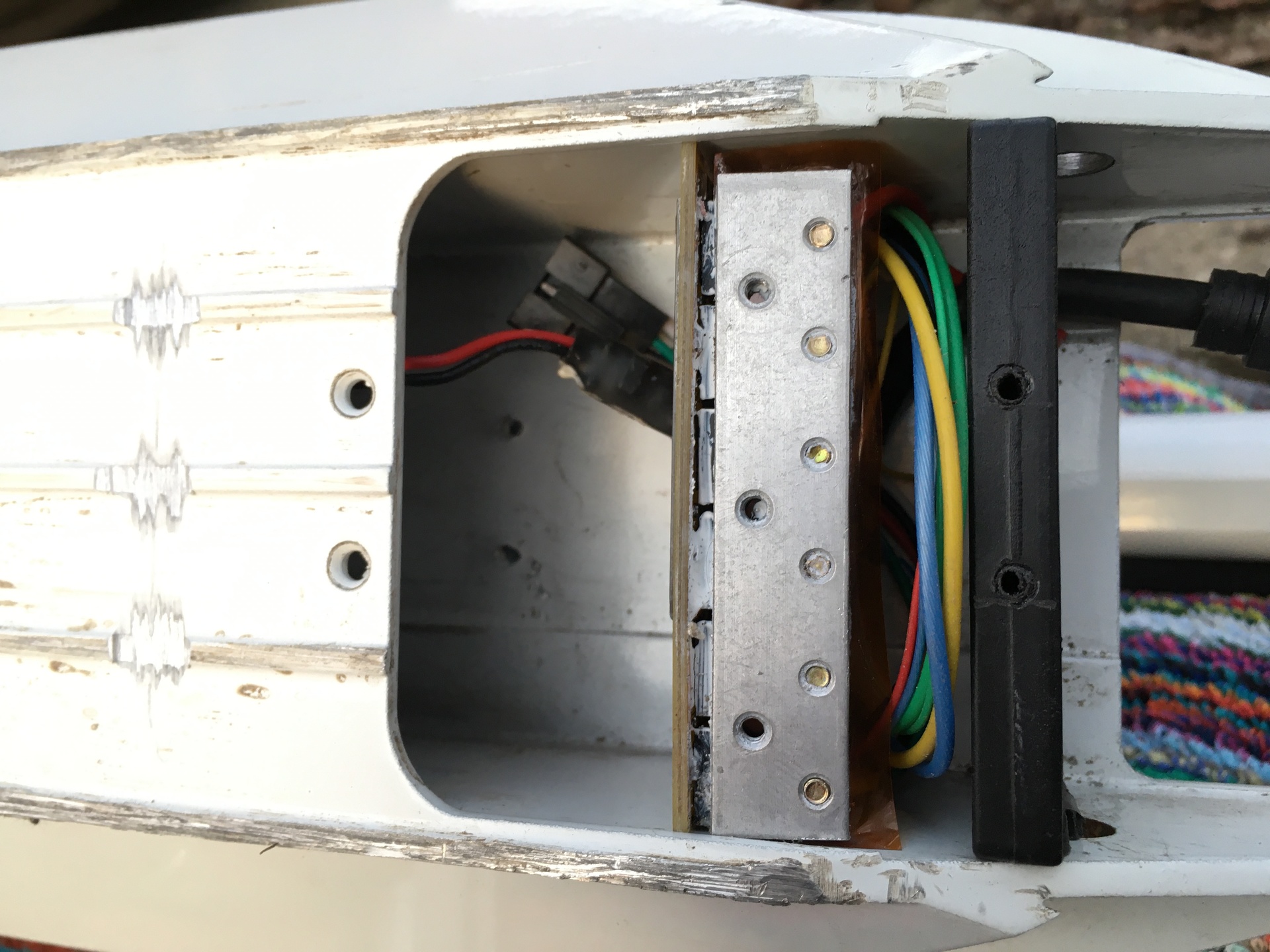
Looks there is enough place behind the battery pack for the rear controller.
The controller almost fit.
If the communication is broken from controller to display,
the roller works further properly, just the information from controller is missing on display. E.g. speed flashes. This means, if I connect the two controllers to the same display interface that way, that rear controller transmitted comminication wire is not connected, the two motor should work well. Just the displayed current consumption value will not be correct.
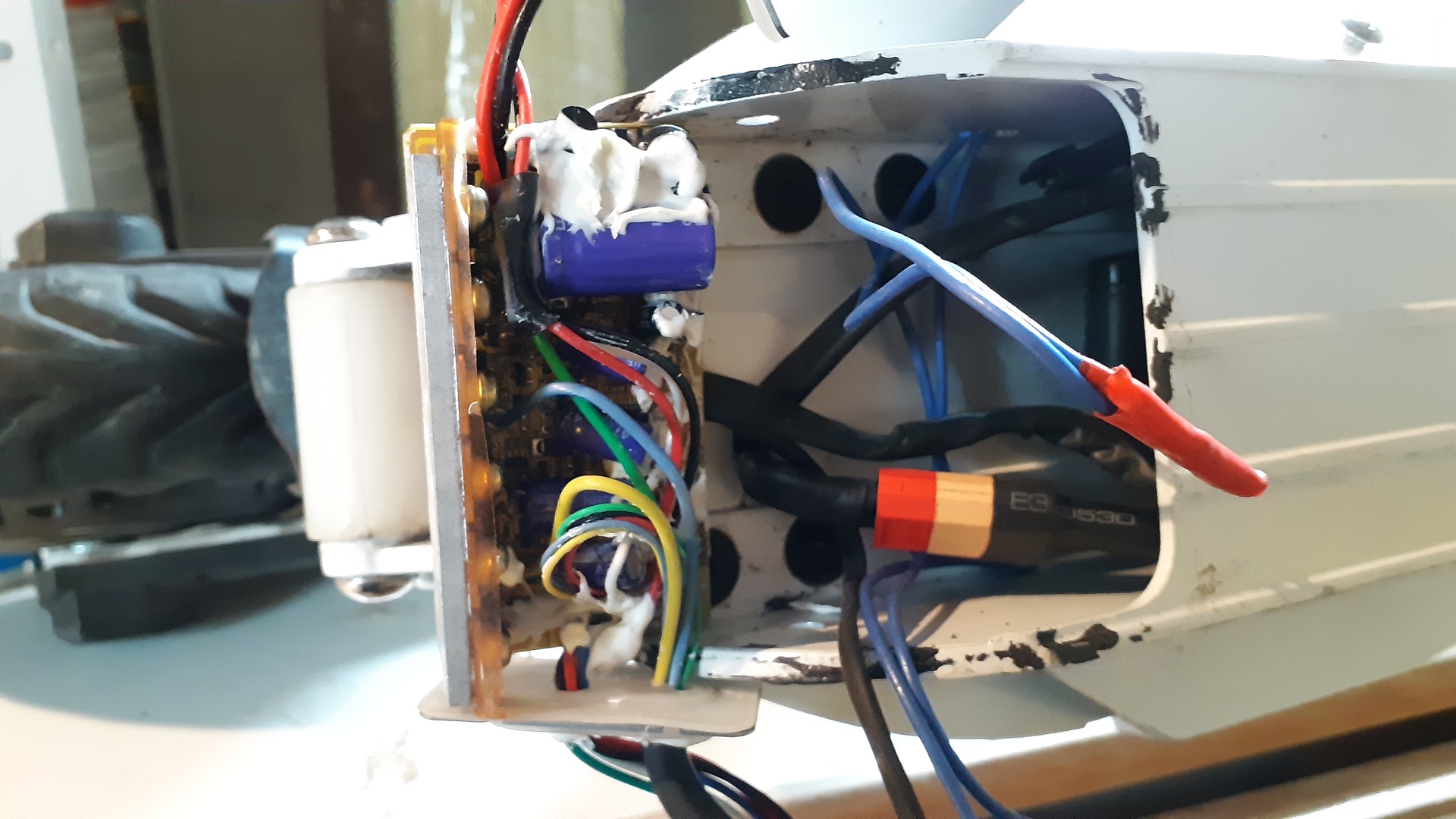
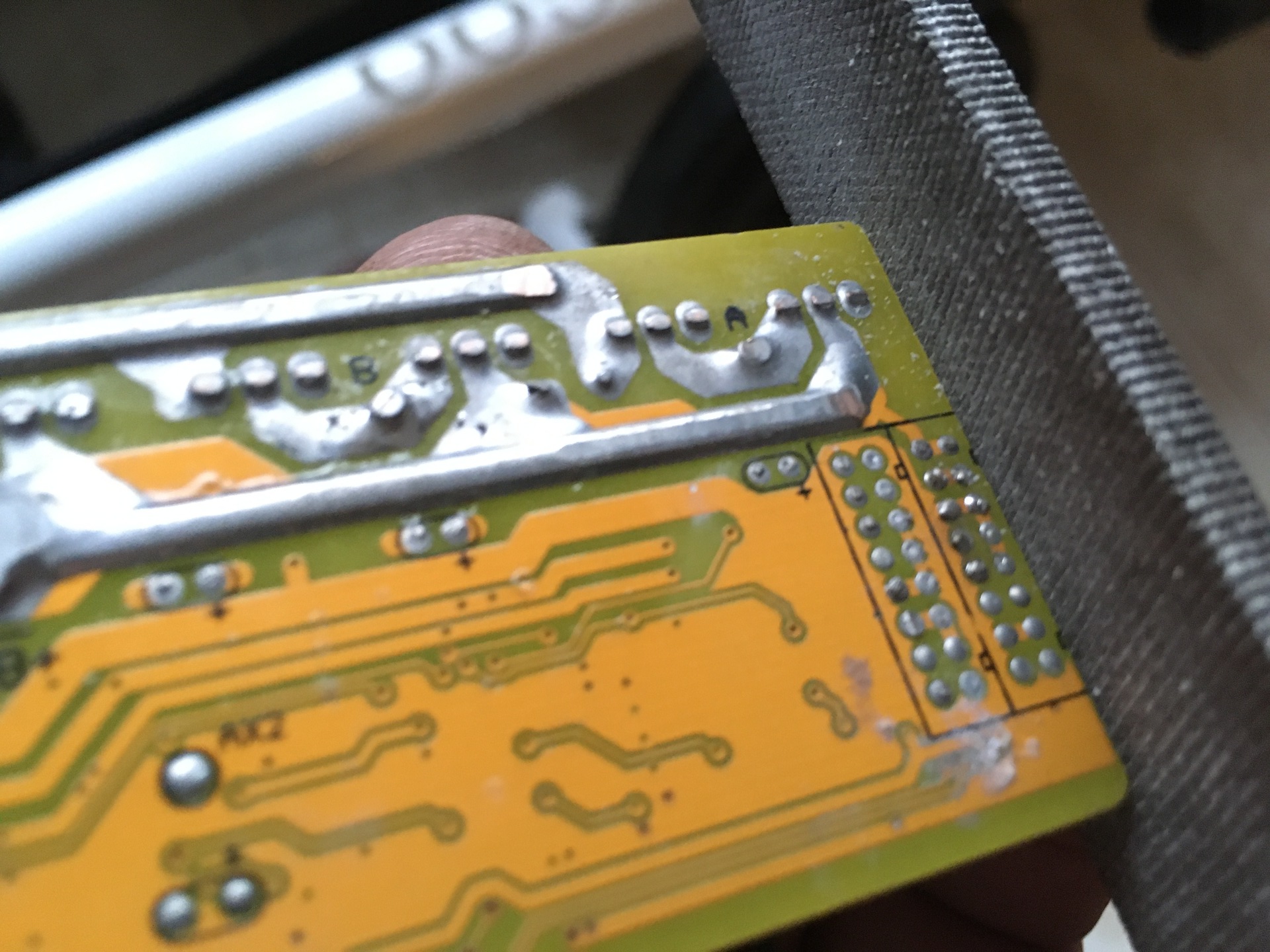
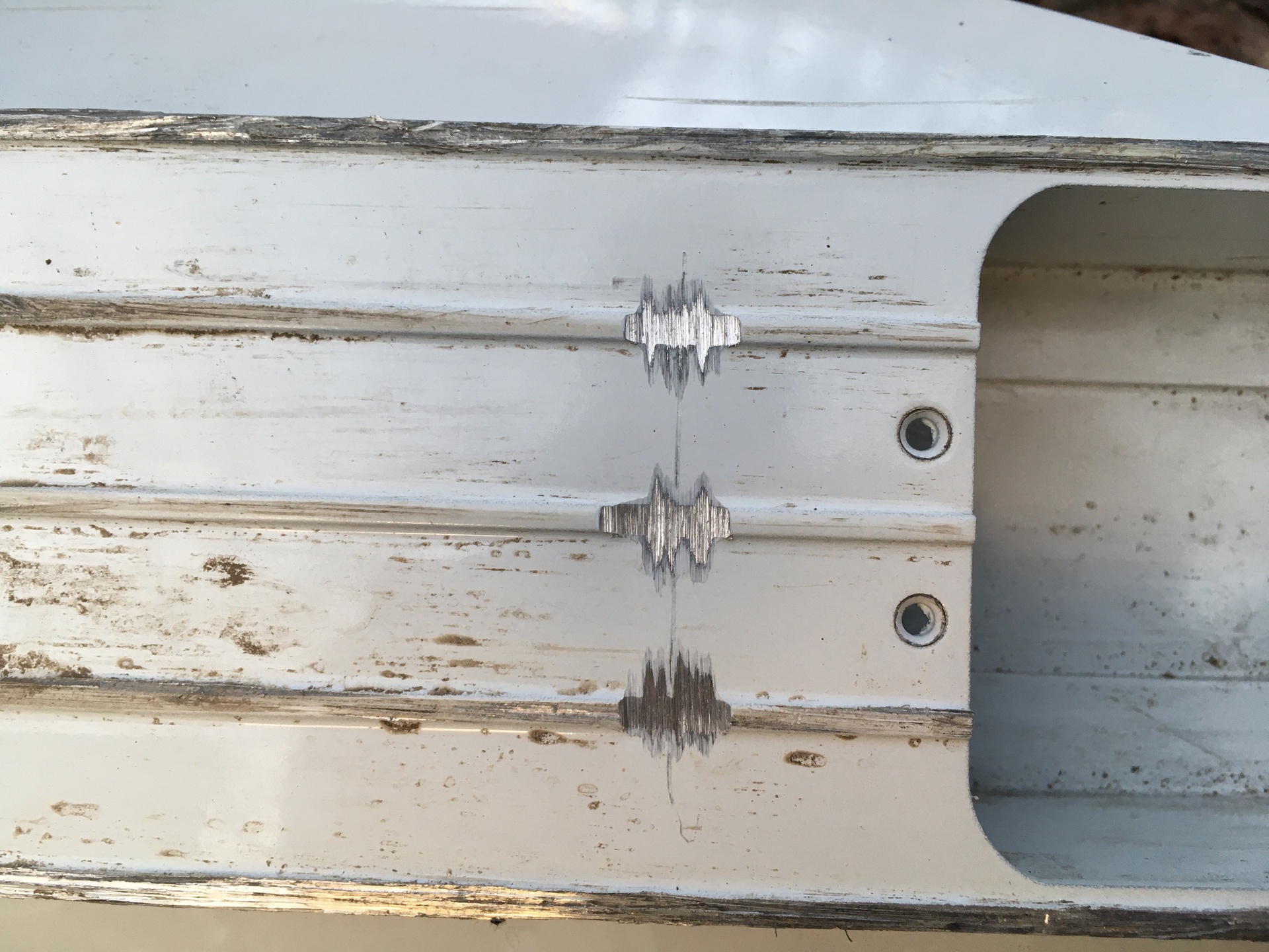
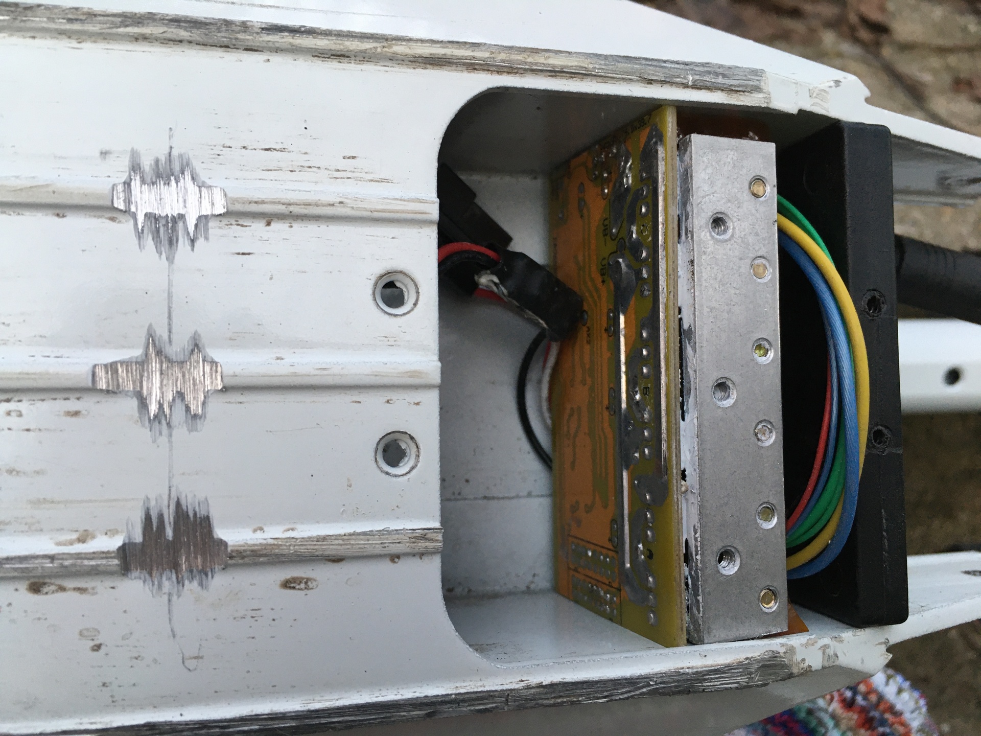
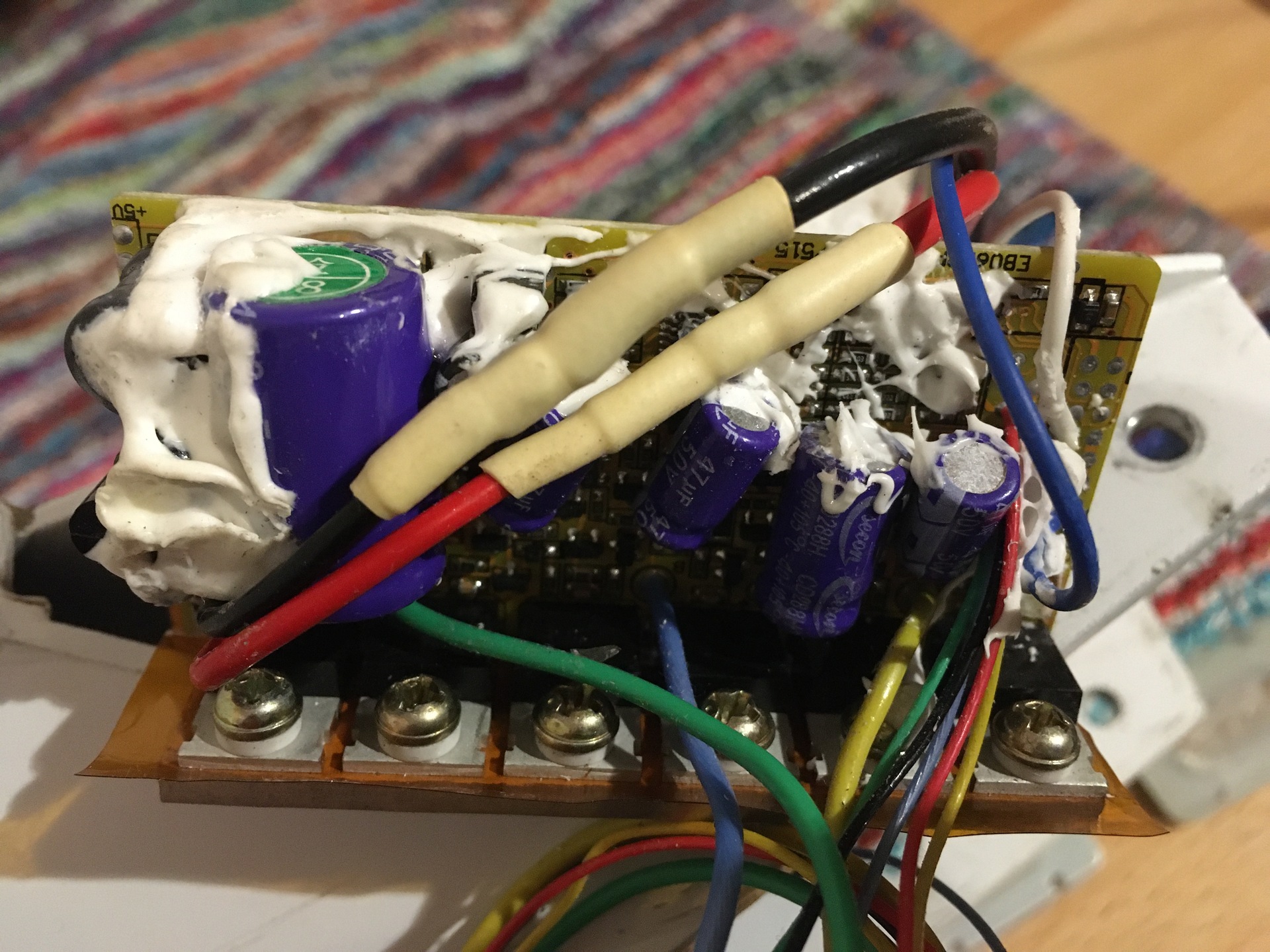
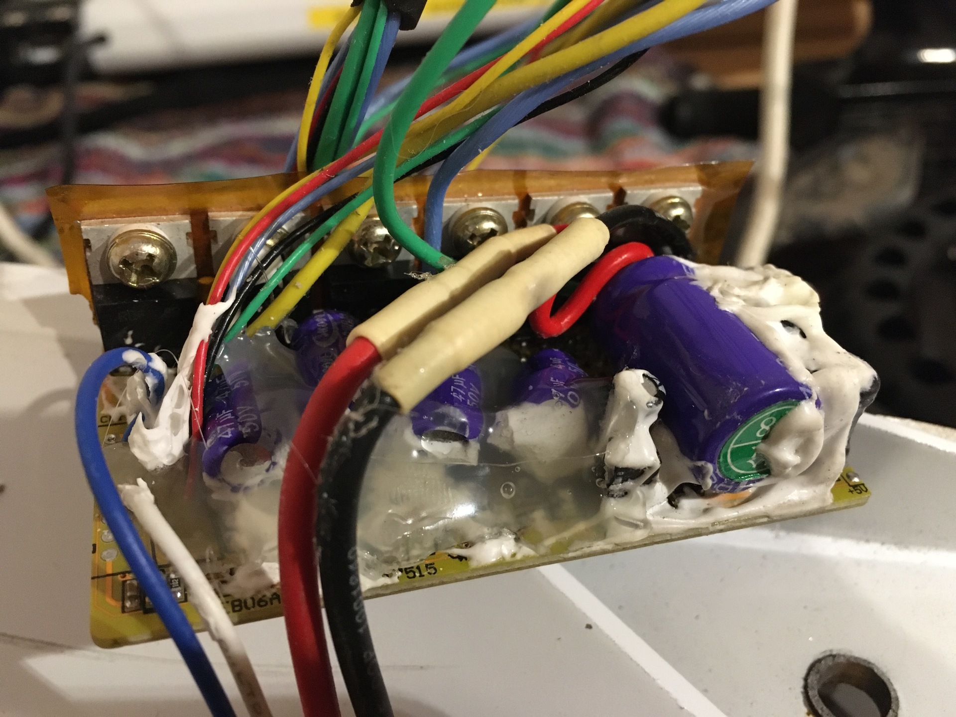
 I grabbed a half millimeter from the edge of the rear engine control board.
Now its size fits to small size.
I grabbed a half millimeter from the edge of the rear engine control board.
Now its size fits to small size.
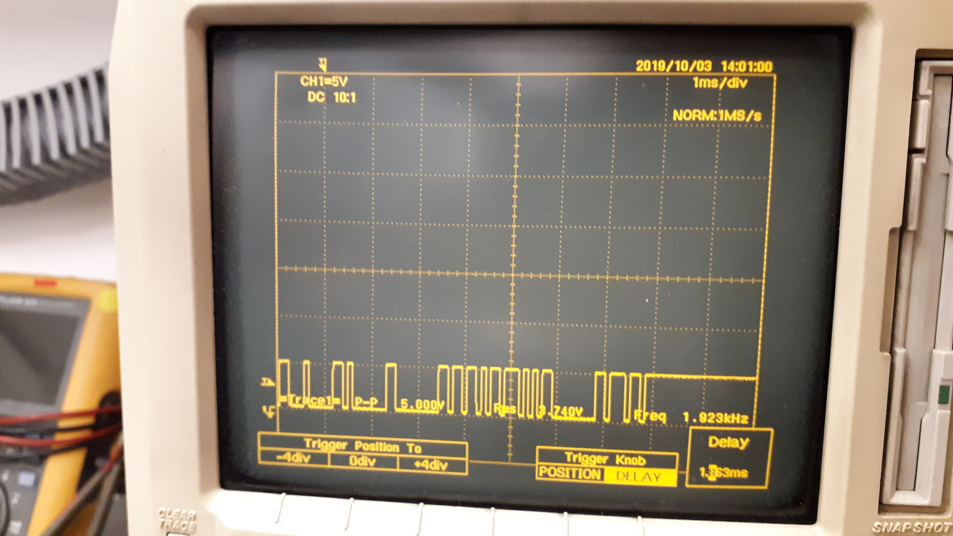
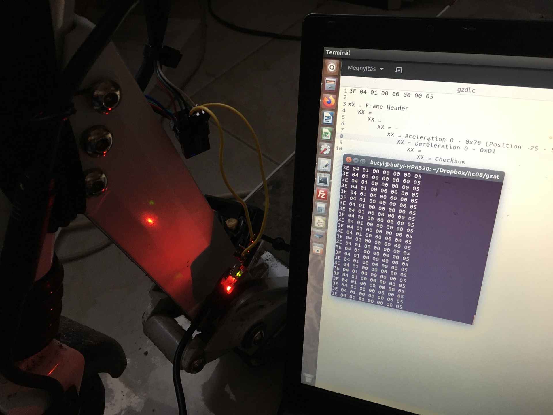
A protocol
Display -> Controller
8 bytes, every 50ms.
Example: 3E 04 01 00 00 00 00 05
Bytes
- 1. Header
- 2. I do not know what is this, it didn't change during my tests.
- 3. Speed level. 1:0x01, 2:0x02, 3:0x03
- 4. Lights, 0x00:ki, 0x80:be
- 5. Aceleration demand 0x00 - 0x78, gradually increasable, but the active range is just between 25% and 50% of the hand arm.
- 6. Deceleration demand 0x00 - 0xD1, 0x0A körül gyullad a féklámpa, 0x10 körül már teljes fék van. Cannot controllable.
- 7. I do not know what is this, it didn't change during my tests.
- 8. Checksum
Power off command: 0xFF 0x00 0x00 after a frame.
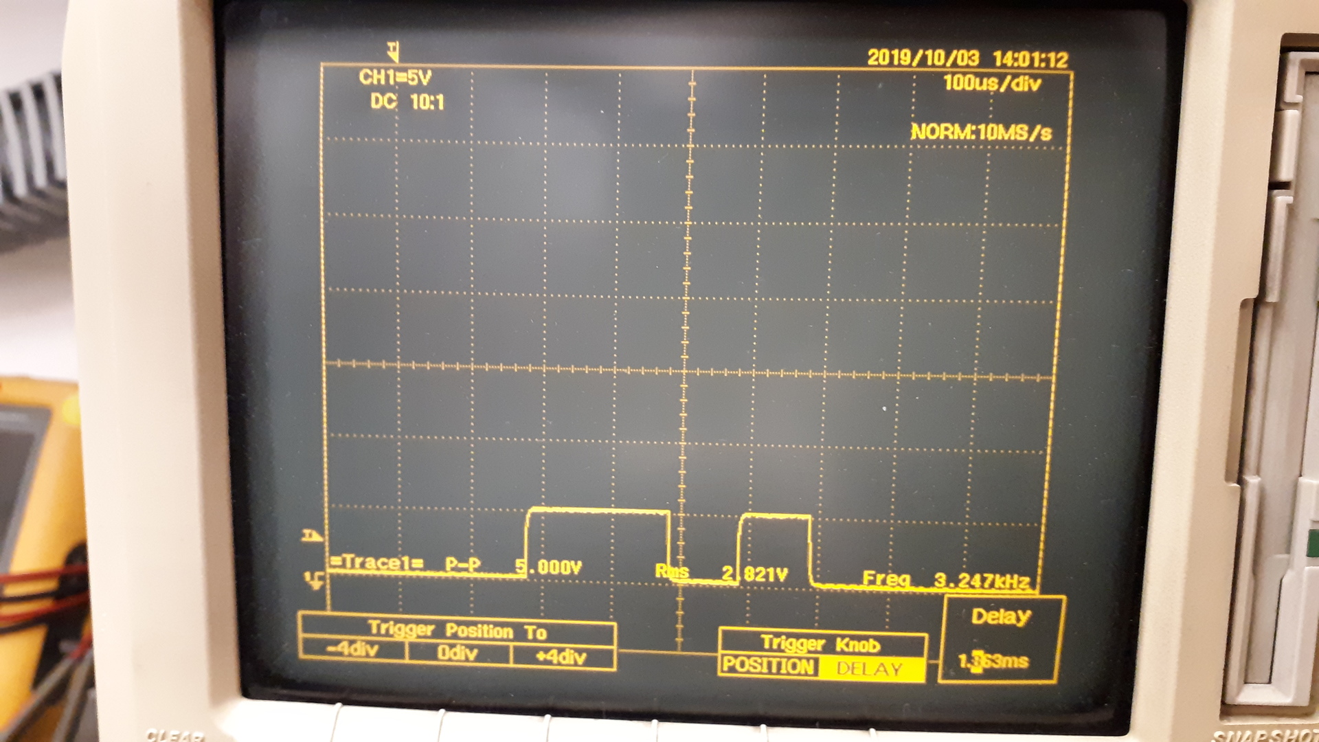
Controller -> Display
11 bytes, every 500ms.
Example: 3C 07 01 00 00 0B B8 00 00 00 CB
Bytes
- 1. Header
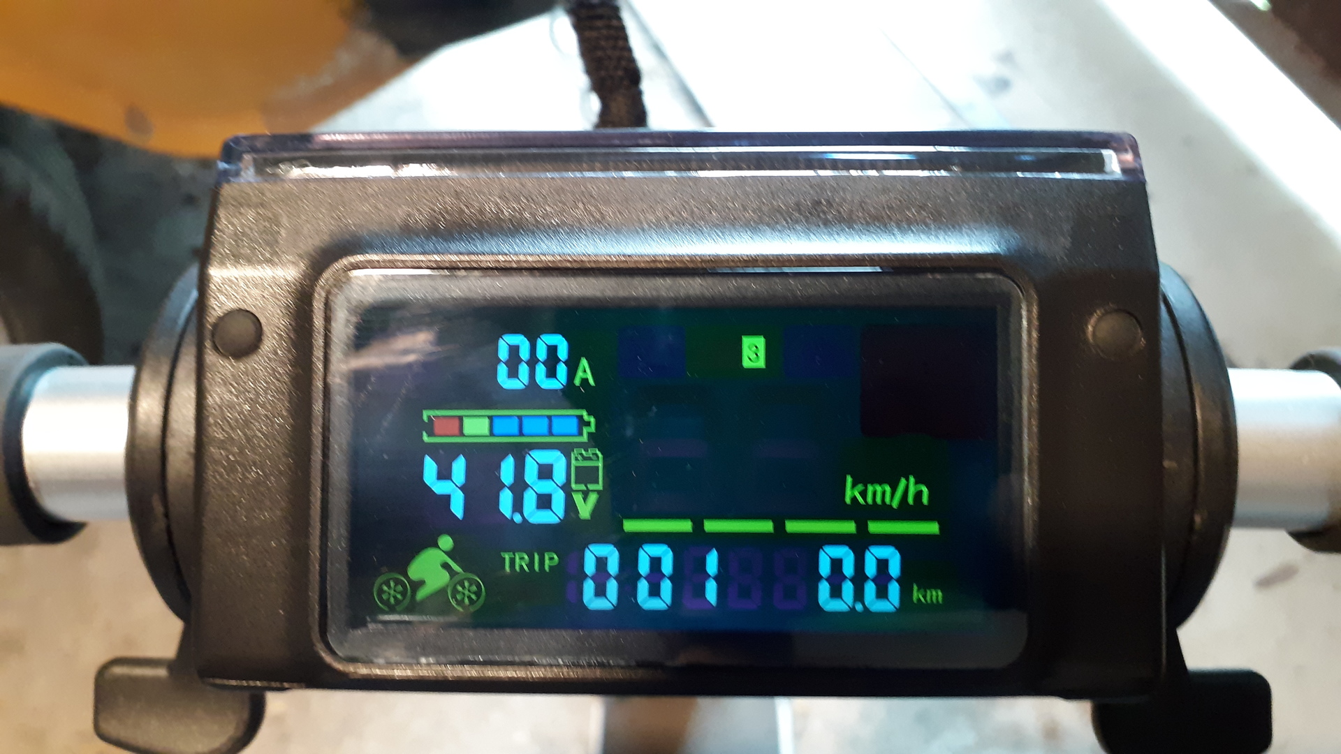
- 2-3. Battery voltage (most likely, I couldn't change it to check is it really that.)
- 4. Control lamps. 0x01: motor fault. 0x04: active brake.
- 5. Current [A]
- 6-7. Time between speed sensor pulses. 0kmh=0x0BB8, 5kmh=0x01CC, 10kmh=0X00D9, 20kmh=0x0070, 34kmh=0x0044
- 8. I do not know what is this, it didn't change during my tests.
- 9. I do not know what is this, it didn't change during my tests.
- 10. I do not know what is this, it didn't change during my tests.
- 11. Checksum
This is the PHP script I have used to check the checksum algorithm: kugoo_s1_communication_checksum_checker_script.zip
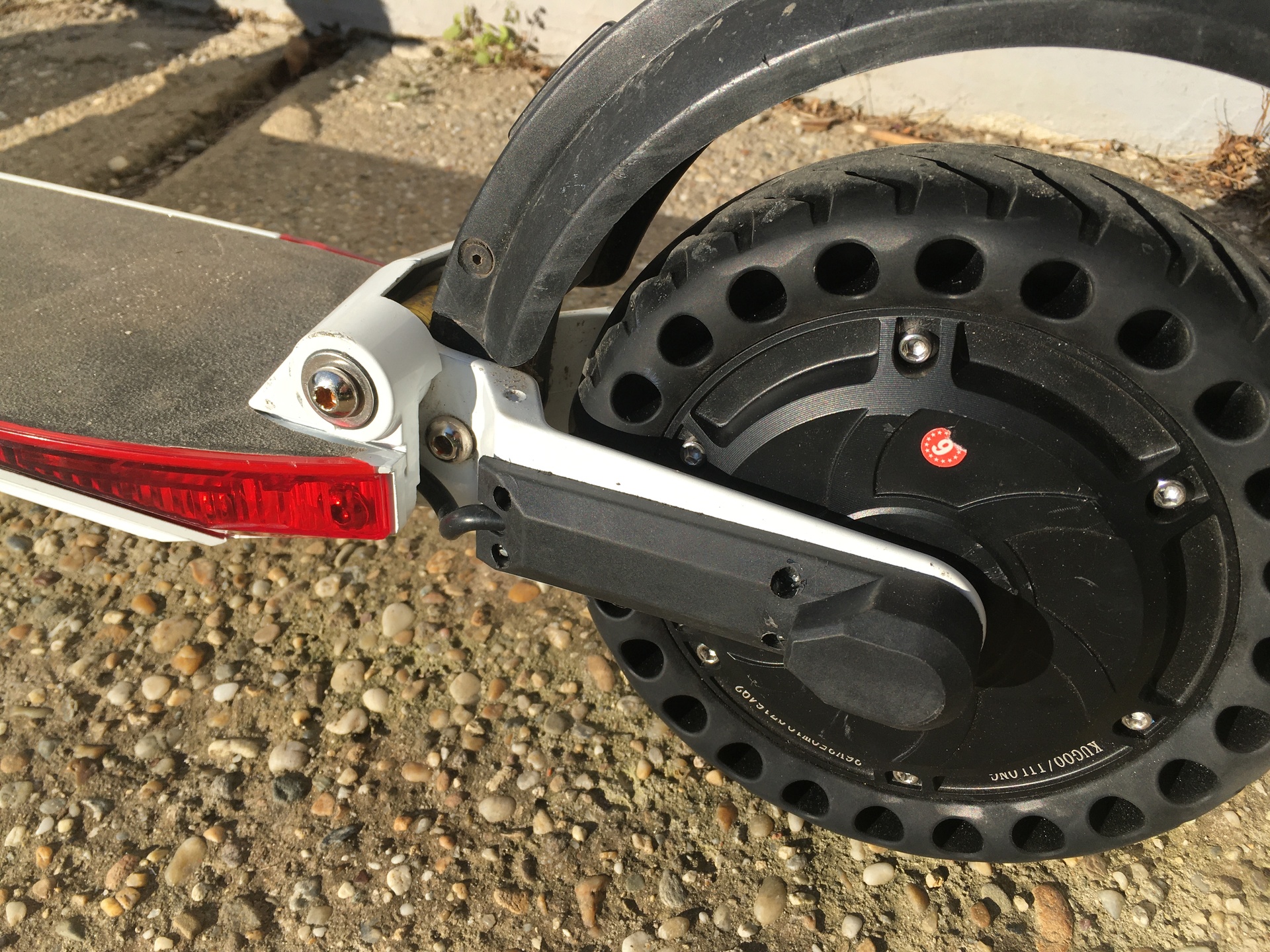
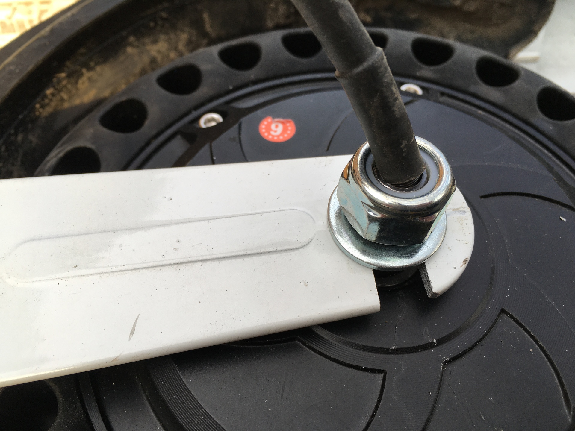
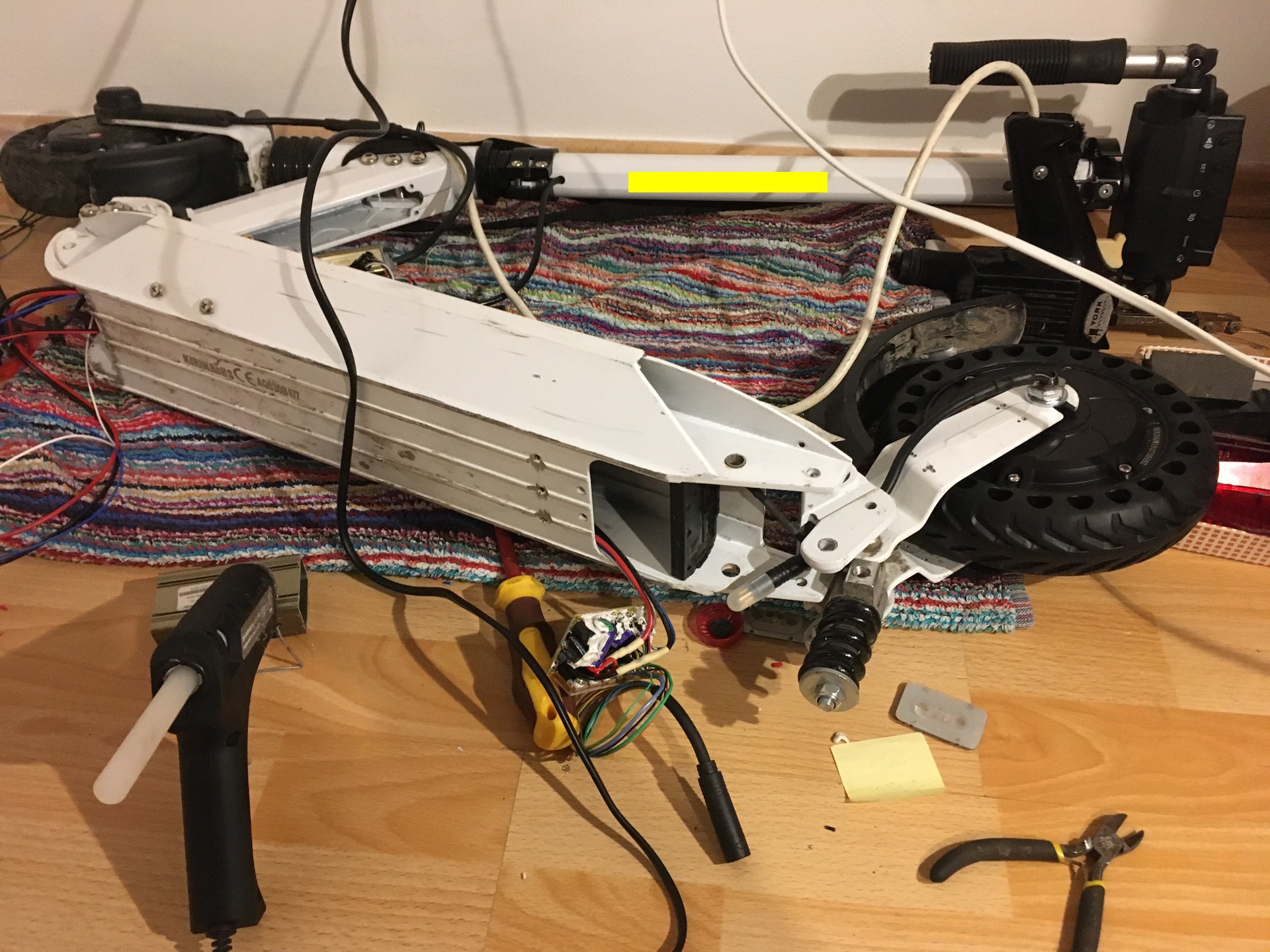
Next is to build in the motor wheel.
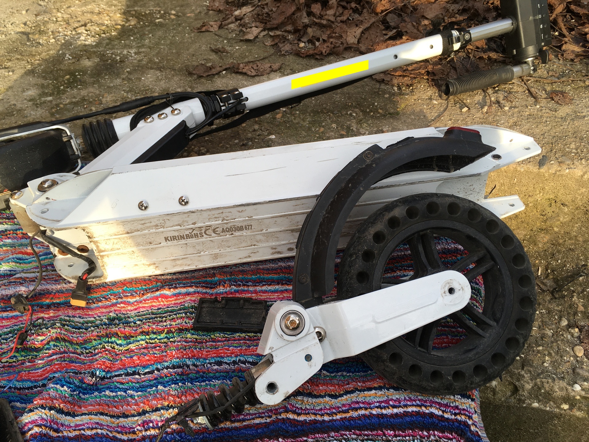
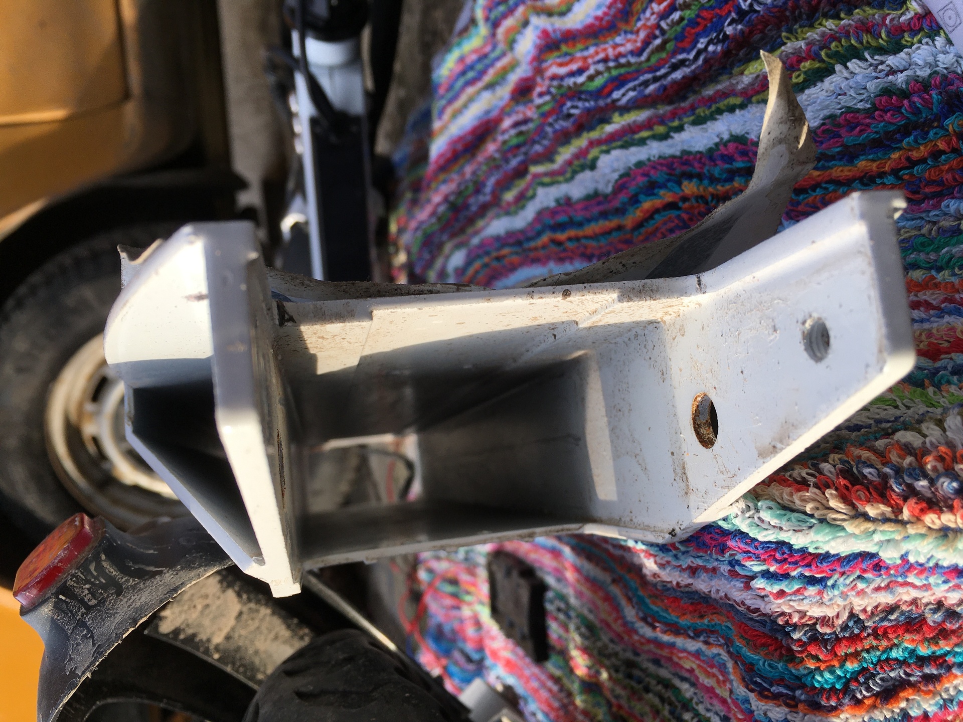
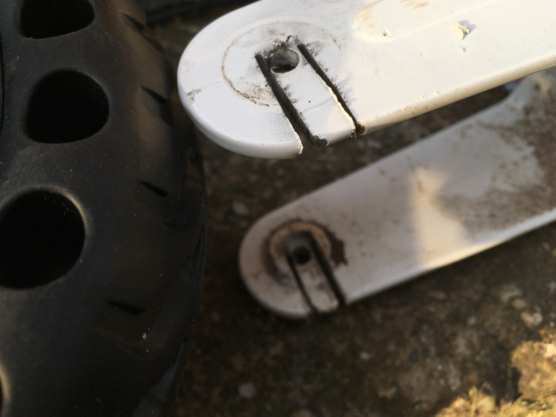
Next is to build in the rear controller circuit.
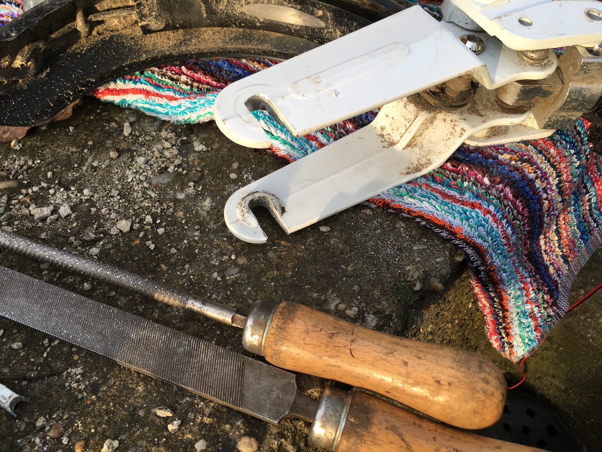
The workshop.
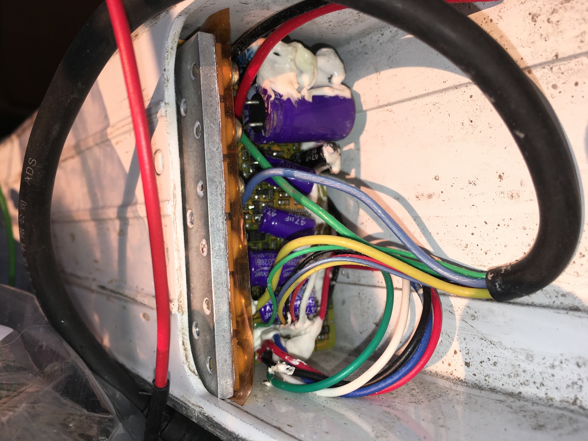
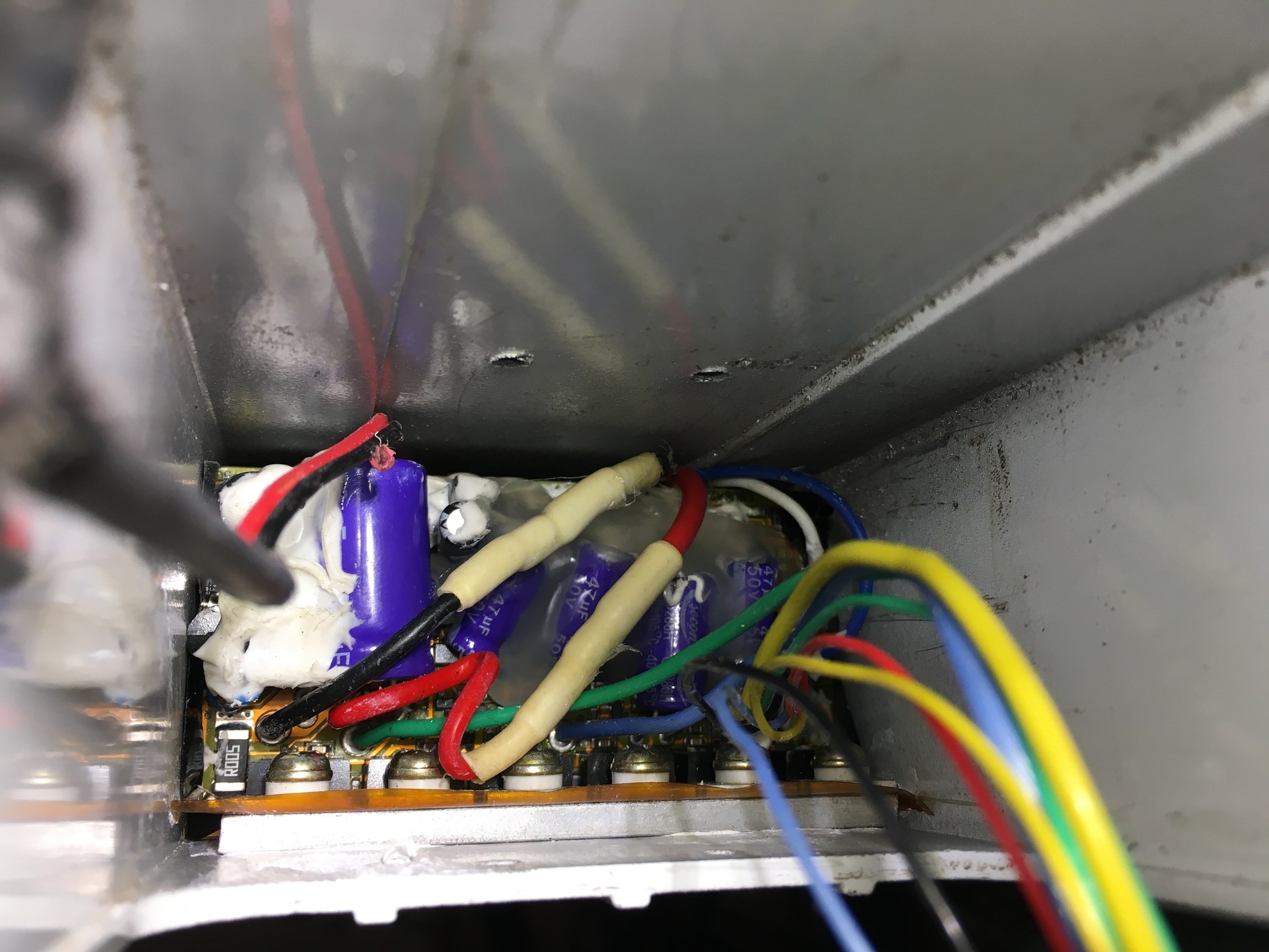
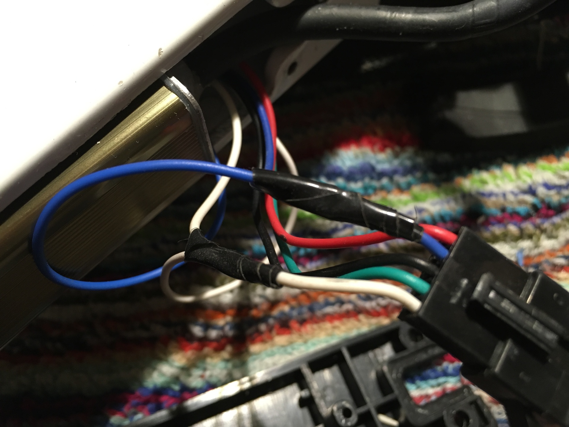
The communication must be connected. I have also connected the switched power line, maybe it is needed for proper power off procedure.
I have removed the other wires.
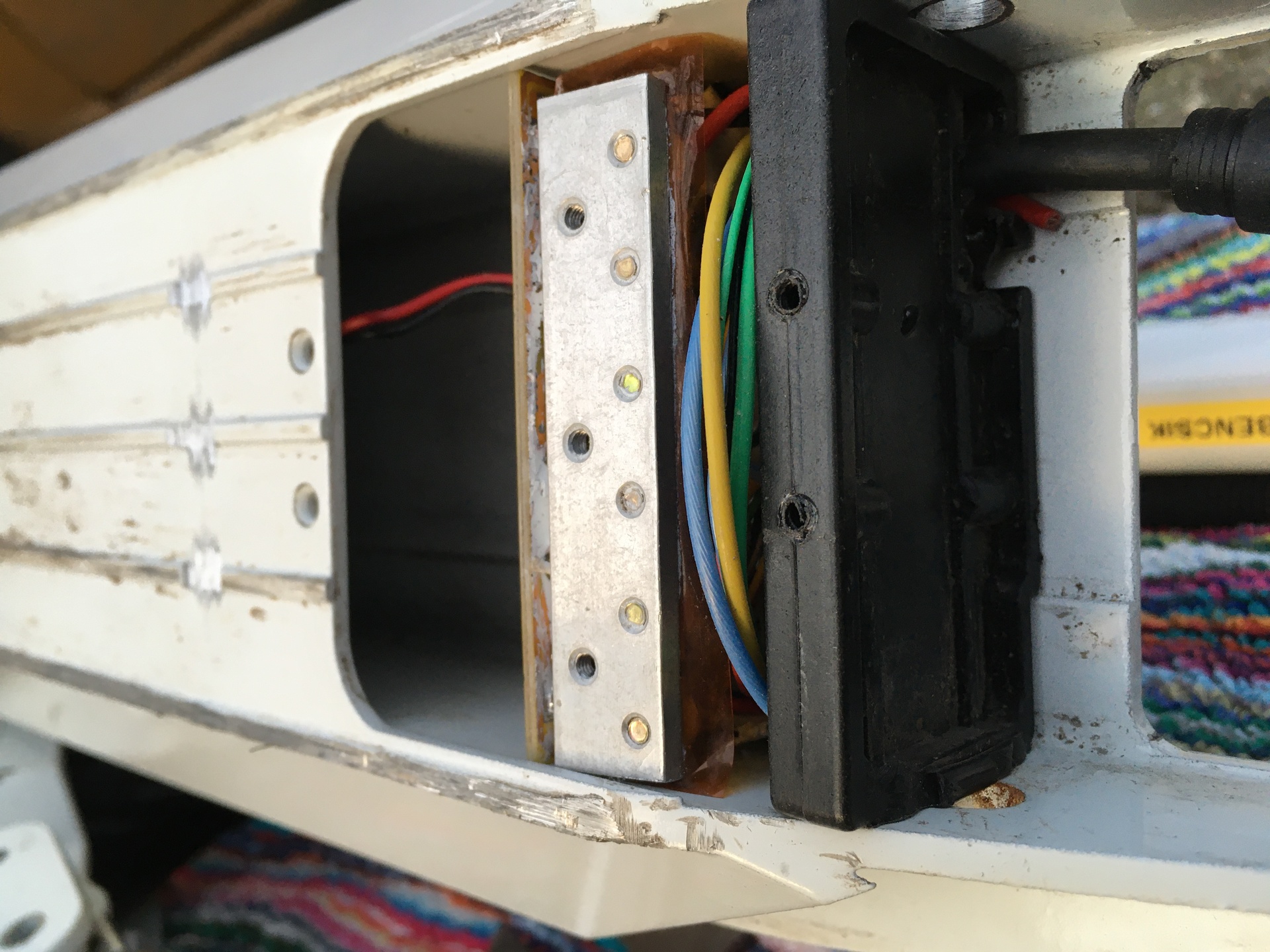
Wires are put into the house.
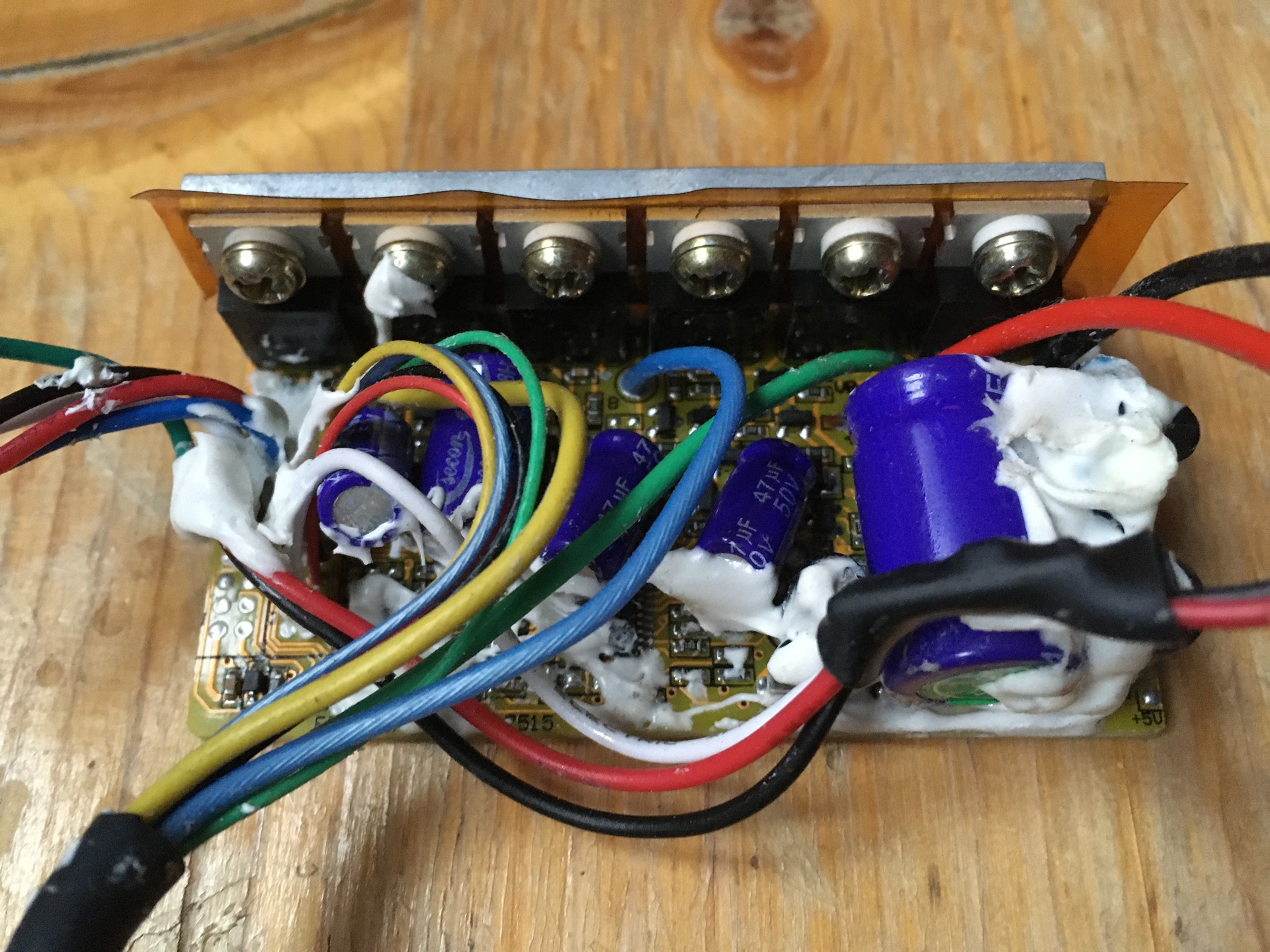
Capacitors are fixed with glue gun.
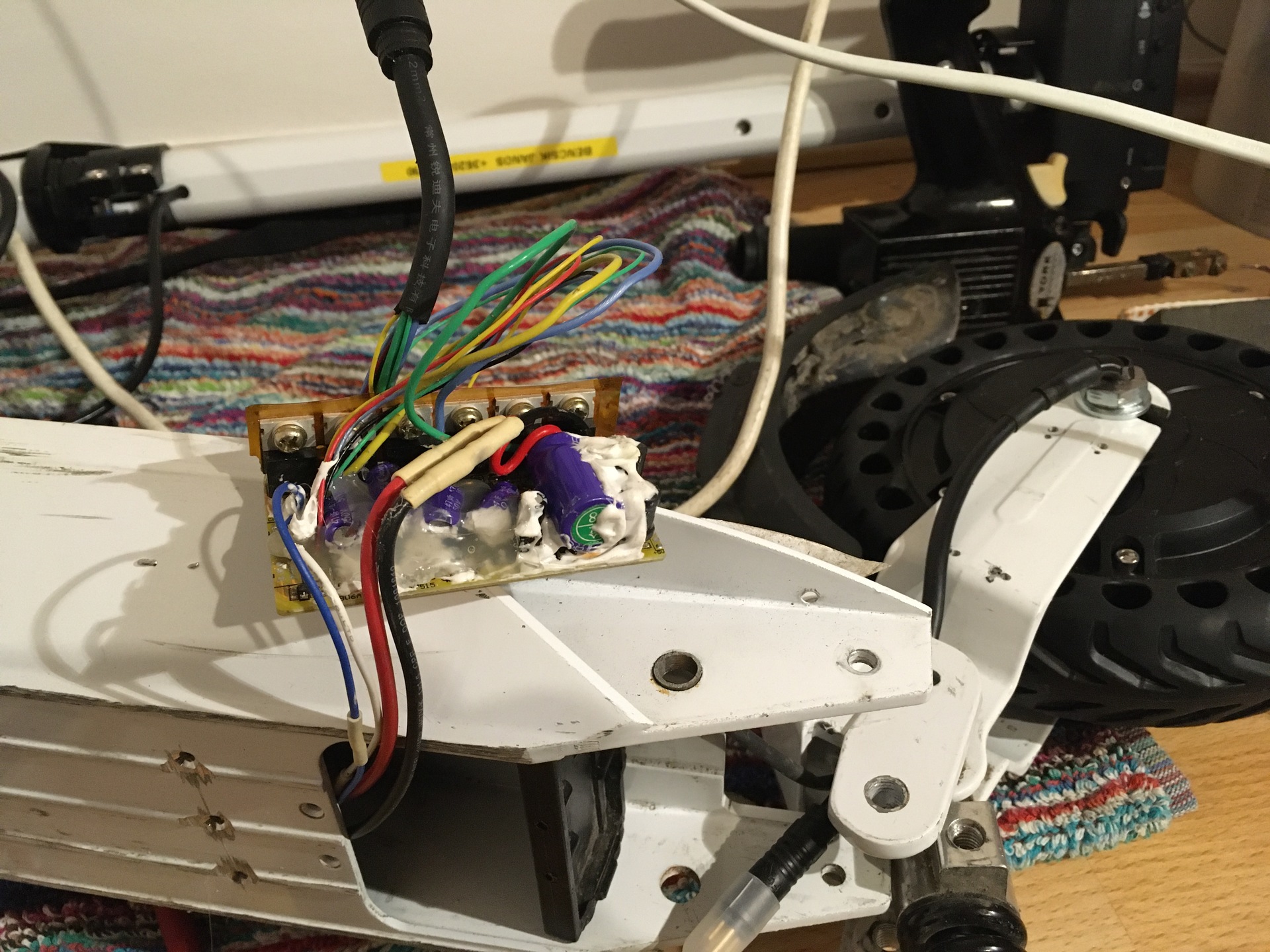
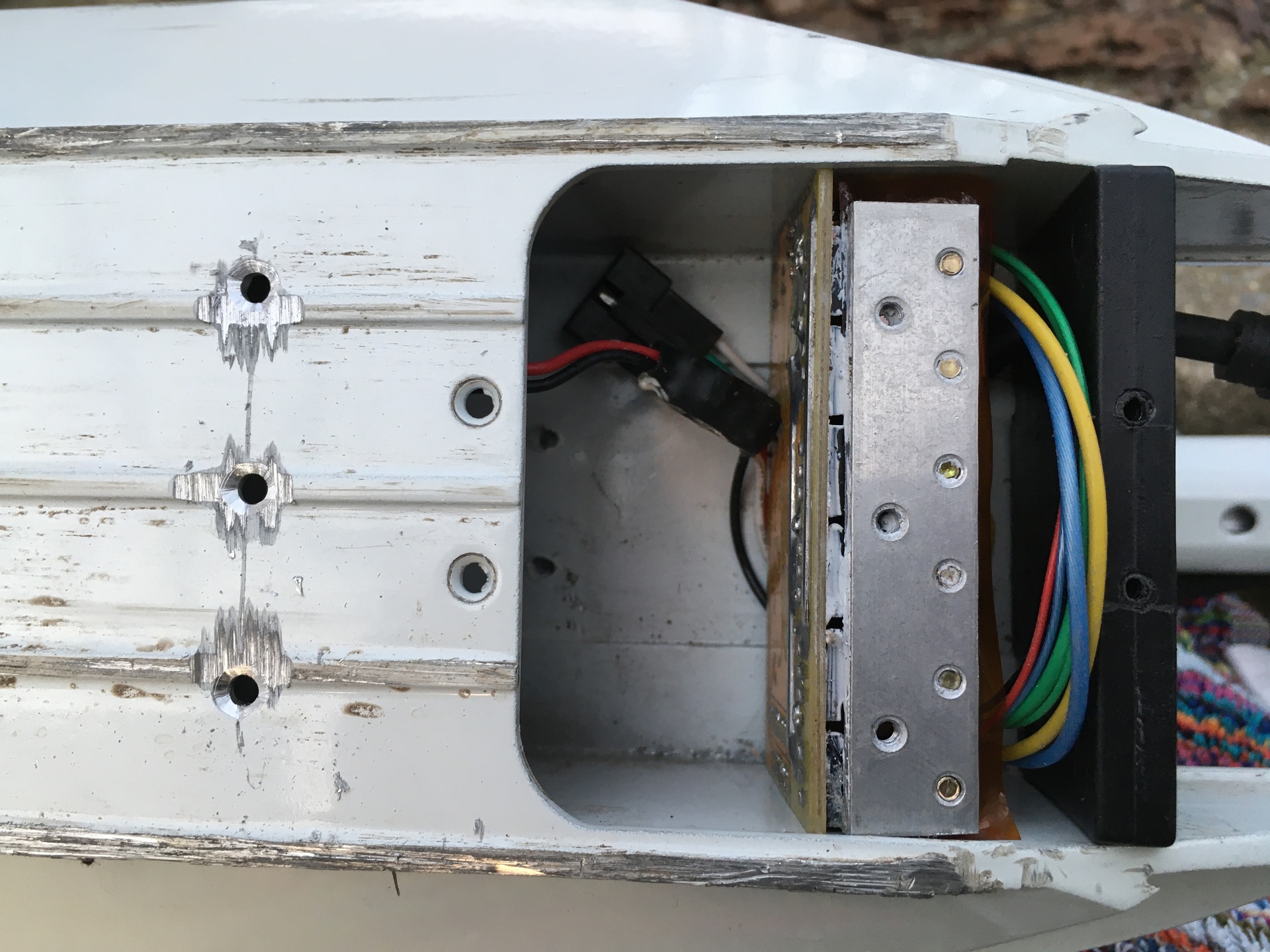
The controller can be mounted into its final place.
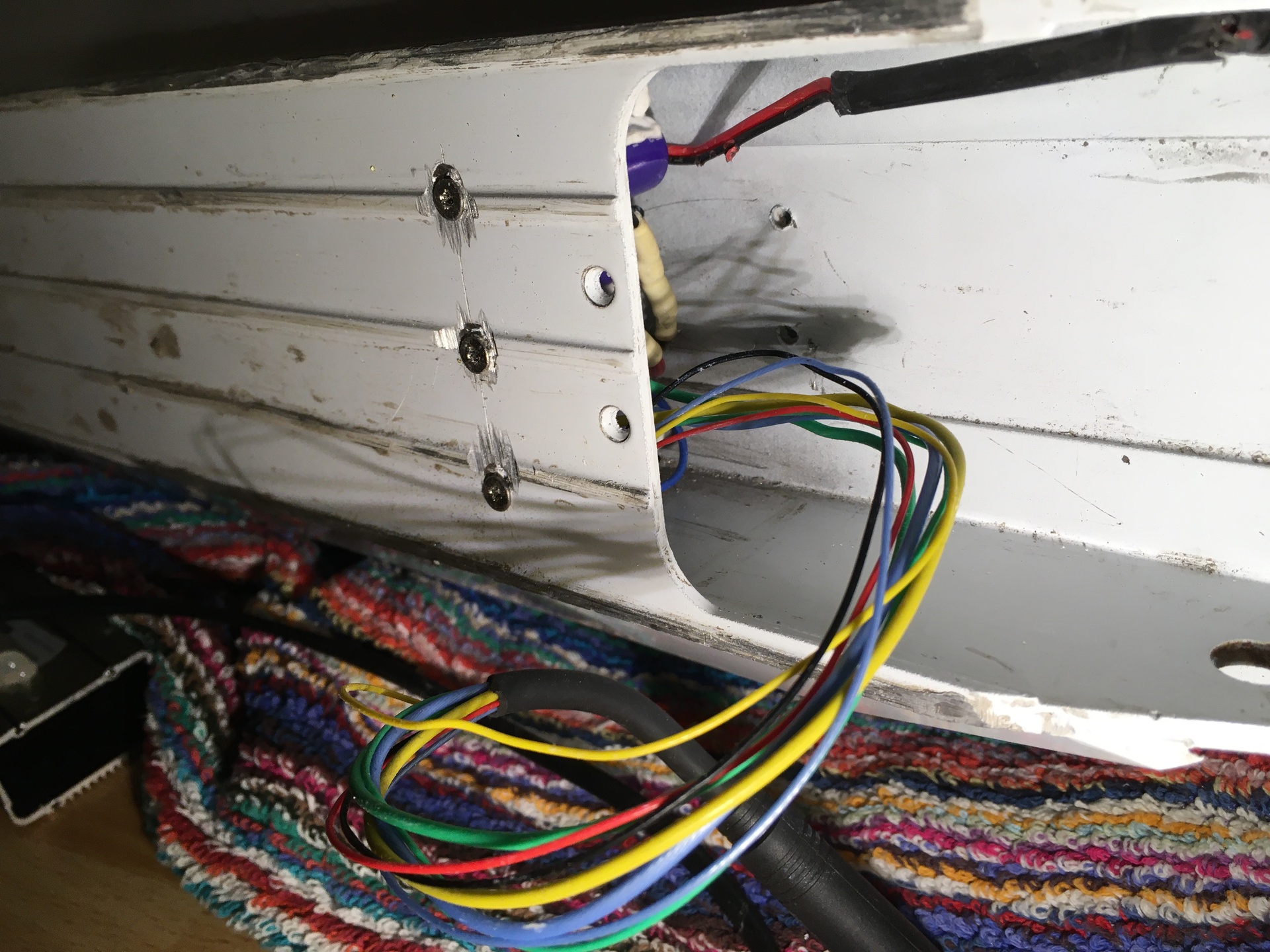
The final soldering and isolating of wires.
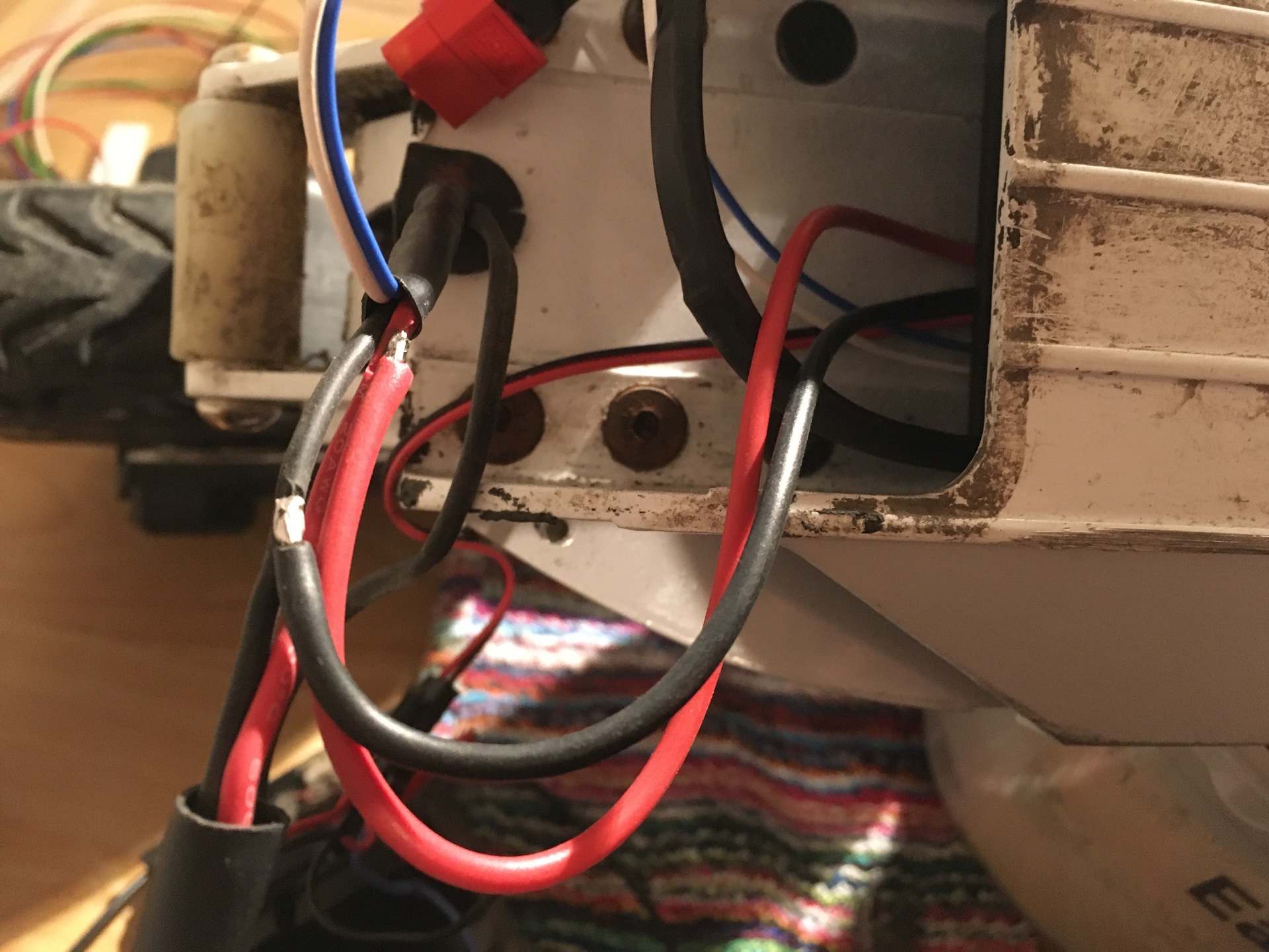
Here is the motor connector.
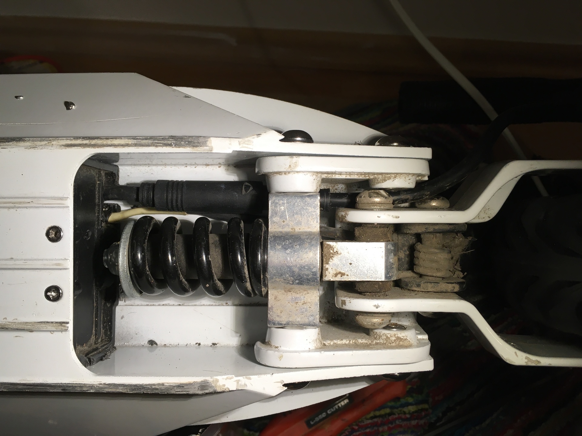
It looks like this.